
------------------------------------------------------------------------------------------------
Special Thanks to the following suppliers & supporters...
Alan Gourlay - My inspiration and mentor. Without the original DIY post of your Stark conversion, I would never have attempted this conversion/build. Your dedication to helping others is unparalleled and I can't begin to thank you enough. Cheers mate!
K20A.org Forum Members - http://www.k20a.org
I would never have been able to figure out the Honda/Acura piece of this engine swap had it not been for you guys. Thanks a bunch for your interest and support. I hope this post inspires others as you all inspired me.
EliseShop - Yvo Tuk - http://www.elise-shop.com
Yvo was absolutely fantastic with not only advice and assistance, but great peripheral conversion/performance parts (both Lotus and after-market) at a phenomenal price.
ENDYN (Energy Dynamics) - Larry Widmer - http://www.theoldone.com
Both Larry and Josh were great when it came to helping a newb assemble a great performance-built K24 TSX engine. In a nutshell, they put together a kit of performance parts and machine work that allowed me to enjoy assembly in my own garage. Thanks guys!
Full Blown Motorsports - LJ, Chuck & the gang - http://www.fullblownmotorsports.net
Bottom line: The Full Blown team has been able to take some of my rough concepts and ideas, and bring them to reality through extensive fabrication capabilities and superior craftsmanship, providing innovative ideas and improved engineering throughout the build process. You guys are awesome! Thanks for attention to detail. I felt like I was always the most important customer and forever welcome in your shop.
SNS Automotive Lotus/Honda Conversion Mounts - Steve Davies (aka Stormin Normin) - snsautomotive@hotmail.co.uk
Thank you Steve for breaking the proprietary nature of 'Conversion Mounts' acquisition and making quality parts available to DIY'ers. Without you, our DIY option would be limited. Love your mounts mate!!
Martyn Tinker Lotus/Honda Conversion Drive Shafts - mfa.tinker@ukonline.co.uk
Thanks for the quality 'bomb proof' shafts Martyn. They work perfectly with Steve's mounts!
Lastly, I'd like to offer special thanks to James Wistanley of Stark Automotive (http://www.stark-automotive.co.uk/elise.html). While I didn't purchase the Stark kit (for K20... not K24), his support during my initial planning was more help than any single person. I'd highly recommend the Stark kit for K20 DIY'ers, as they provide a kit and support that includes everything you'll need to convert your Lotus Rover to Honda.
--------------------------------------------------------------------------------------------------
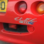
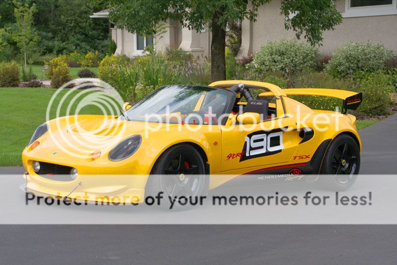
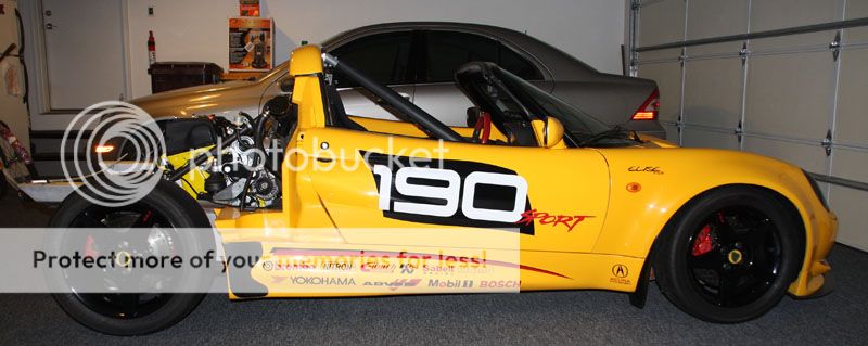
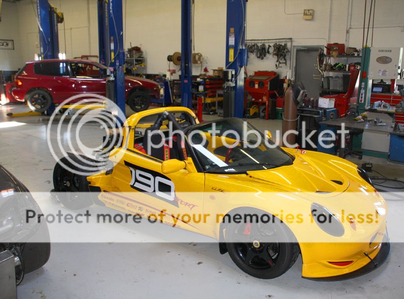
The Car: 1999 Elise Sport 190 (Series 1) - Factory Track Prepared - 1,600 lb Aluminum Lightened Chassis
Primary Use: Performance Driving / Track Days
Existing Engine: Rover 1.8L VHPD (est. 175whp)
New Engine: NA Acura TSX 2.4L K24
Performance Goal: 280whp/210ft-lb Tq
------------------------------------------------------------------------------
------------------------------------------------------------------------------
Why DIY?
Initially, many may think the primary motivation to take a DIY approach is 'cost savings' . For some, that may be. For many others, it's not that at all. In fact, I'm pretty sure I went WAY beyond what it would have cost at a turn-key installation shop.
No, my reasons were different. I wanted to do a conversion to the level of detail & care not traditionally delivered by a third-party installer. Let me qualify that statement by stating that most 'turn-key shops' are more than capable of doing a conversion that way, but might only go to that level of detail and care on their own car, or for someone with a boatload of disposable income.
I chose DIY because simply put... I love my Lotus, and because of that fact, my conversion is/was a labor of love. I took my time and and enjoyed the experience, and as a result my Lotus is unique and a reflection of my passion for the car. Because I chose this path, I now know my Lotus intimately, and this new-found knowledge enables me to better understand potential issues that may arise in the future. No manufacturer's kit is perfect, and issues may arise, be it mechanical and/or electrical. It's nice not to be married to a shop that may not be there a decade from now. Just my humble opinion here, but never believe that a third party install shop will treat your car with the same passion and level of detail that you would.
Lastly, I'm not a mechanic by trade, but rather a sales/marketing desk jockey. I say this because I believe most Lotus owners are not professional mechanics, but have a passion for the car. If you can turn a wrench and read a schematic diagram, you most likely can do this conversion. You may not do it as fast as a shop who does it every day, but if you have patience and take it one step at a time, I believe most can do it just as good (and many of you even better).
Feel free to contact me directly with questions or additional contact information. There may also be other website/forums I can direct you to that might provide additional information and detail.
Good wrenching!!
- Ken
-------------------------------------------------------------------------------------------------------------
Video Link to laps at Road America
Here's my first few laps at Road America this past July with the Rover engine (just before it blew). Awesome track. Can't wait to go back this next spring! I'll post a comparison video of the new TSX engine once complete.
http://vimeo.com/16341266
-------------------------------------------------------------------------------------------------------------
A few months back, I sourced the first component needed... an engine.
K24A2: 2004 Acura TSX
* Displacement: 2,354 cc (143.6 cu in)
* Power: 200 PS (150 kW; 200 hp) @ 6800 rpm
* Torque: 232 N·m (171 lb·ft) @ 4500 rpm
* Bore: 87 mm
* Stroke: 99 mm
* Redline: 7100 RPM

Actually, I was quite lucky finding this particular engine. Most 'Frankenstein' hybrid engines (K24 long block with a K20 head) require two separate purchases, but the Acura TSX (2004-06) came factory with the desired combination... Long Block with iVTEC Head (so no need to get the K20 head).
Engine Cost: $1,800. It may not look pretty, but considering nearly all the internals will be replaced, the only things we really wanted were the block and the head. Most everything else goes in the garbage.
Build Strategy: I have a few options here. NA or SC'd. Also, I could also de-stroke the engine to where it will rev to 12.5Krpm, but at the expense of more frequent rebuilds.
Some may be asking... why K24 vs. K20? The simple answer, personal preference. At 1600 lbs, I didn't want to take the fun out of driving the car (SC'd = 325+hp) so I settled on a performance goal of around 275-280whp. Fun... but not insane. I didn't want an engine that was so tweaked, I only got 5K miles out of it. I wanted longevity and reliability as a priority. Second, I prefer a NA aspirated engine, but a NA K20 would really only give me a few HP more than my VHPD. Considering the expense involved in the conversion, I want a little more for my money. A performance built K24 will easily meet that goal.
Since I recently blew the head gasket on my VHPD (at Road America in early July), I figured it's time to officially start the conversion process...
Removed Wheels and Undertrays.

Removed Rear Clam.

VHPD Engine Exposed

Removed Air Intake (Note Oil in Overflow Bottle)
Removed Rear Suspension Components and Exhaust

Strap-Up Engine Trans Assy

Turn Assembly Gently and....

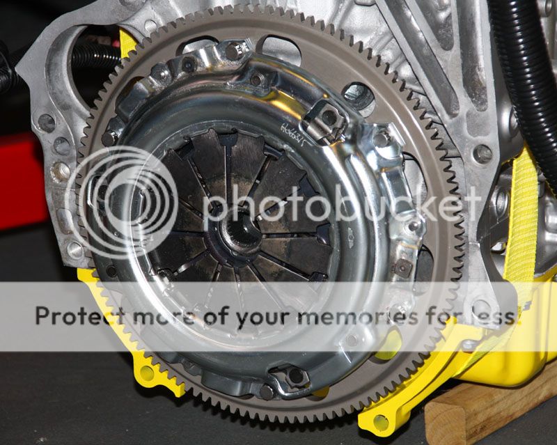
VHPD Removed

Milestone 1.... Complete.

Now let's get this cleaned up and build the engine.

------------------------------------------------------------------------------------------------------------------------------------------------
K24 Conversion Strategy: Surprisingly, there is not a ton of difference between a K24A2 (TSX) and a K20A2 (RSX Type S -or- Euro Civic Type R). Aside from the obvious displacement, the only significant physical difference is block height. The K24 'Long Block' is 19mm taller than the K20 block. Since most conversion kit mounts are made to fit a K20, I had to take this into consideration when fitting a K24. Here's a photo taken out of the back of my van when I picked up the K24.

In order to better understand the difference in what might be required for the front engine mount, I super-imposed a photo from a K20 to see how it matched up. Notice the chain case bolt-hole pattern is different from the two engines.

Notice the bolt hole pattern difference? Because it's popular to swap the K20A2 (RSX Type S) for the K24 (TSX), I found that there are some custom front engine mounts engineered to adapt the K24 to the K20 engine mounts in the K20 RSX Type S. This one is offered from Club RSX (Aluminum Light Weight).
http://www.clubrsx.com/cr/PRR-P800B.html
If you're looking to save a few dollars, you could also opt for a K24 CRV mount for $30. It basically allows you to bolt directly to the K24 chain case, and adapt to a K20 mount. (pictures to follow).
As for the transmission, you'll need to use a gearbox from a RSX Type S ('02-'04) or the Euro Civic Type R. It bolts directly to the K24 (or K20) with no issues. We'll discuss tranny preparation in the next post.
I want to build a K24 that will provide a bit more power over stock specifications, so step one is dis-assembly of the TSX.
Remove front pulley.

Remove Cams and Valve Train Assembly.

Chain Case Removed.
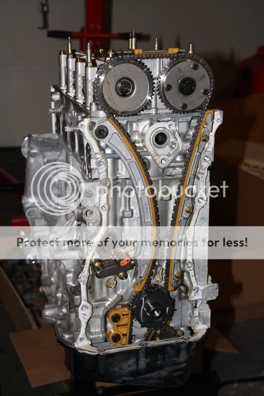
Cylinder Head Removed.

Carbonized Pistons.

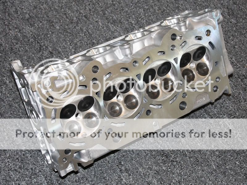
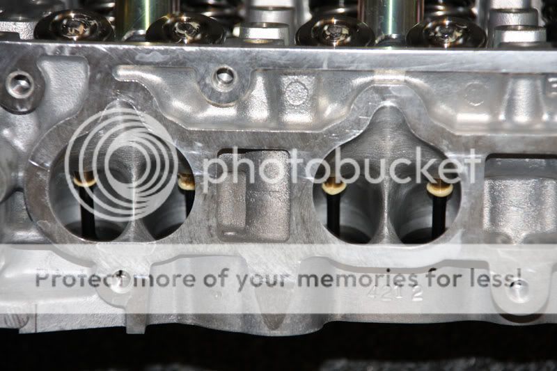
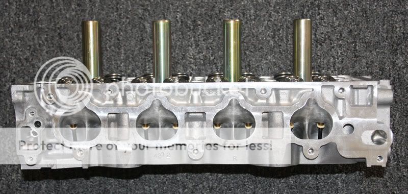
Cylinder Head.

Once teardown was completed, I boxed up the crank, block and head to send to ENDYN Racing in Ft. Worth, TX. Endyn has been building Honda racing engines for 20+ years (working directly with Honda Racing) to get the most performance out of various engines. Their website is http://www.theoldone.com and Endyn's owner (Larry Widmer) is recognized as the one of the best performance machine/build shops on the planet.
After several discussions with Larry, Endyn will build me an engine kit built to extreme performance specifications that I can assemble in my own garage. In short, I don't have to worry about all those bearing tolerances, end gaps, and other techno-guru specs that aren't my specialty. He'll provide me all the parts to assemble a coordinated racing engine, but in a kit form so I can enjoy the build experience in my own garage. Next.... the specs of what I chose to have Endyn build for me.
------------------------------------------------------------------------------------------------------------------------------------------------
Now for a little about the K24 Performance Build...
The Block: Endyn will bore and hone the block to 87.5mm (no need to sleeve) with deck plate. This bores the cylinders properly without ovalizing cylinders (deckplate). Evidently, without the deck plate, cylinders will warp slightly once assembled creating 'out of round' cylinders. The deck plate prevents this from happening. They will also deck the engine block, ensuring proper fit to cylinder head.
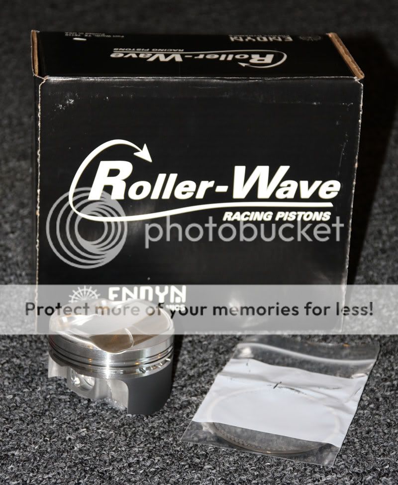
They will provide 87.5mm RollerWave pistons (12.5:1) and coat piston skirts (Endyn custom design for the K24). Piston Rings will be installed with proper end gaps to ensure proper fit. Custom Crower MaxiLite Billet Rods (not Brian Crower) are provided with custom fit wrist pins and rod/main bearings fit to within .005 in.
Line Hone Main Bores To Spec
Cometic Head Gasket to 87.5 mm bore (custom)
Fit Rings/Rod Bearings/Main Bearings to Spec
Cylinder Head: Full Racing Performance CNC (Port match to Skunk2 Intake Manifold)
Valve Job, Decking & Assy, Premium Tapered Manganese/Bronze Guides, Hone Fit Valves
New Valve Seats
Black Nitride Coated Flat Face Exhaust Valves
Black Nitride Coated Flat Face Intake Valves (36mm) , +1mm larger
Eibach Valve Springs
Chromoly Retainers
Valve Spring Seats for Dual Springs
Split Locks
Valve Stem Seals
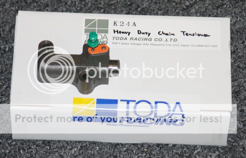
Custom Endyn Stage 2 Camshafts - Sized to provide performance but easy on the Toda chain tensioner.
K20 Oil Pump - CNC Port/Polish and machine work to fit K24.
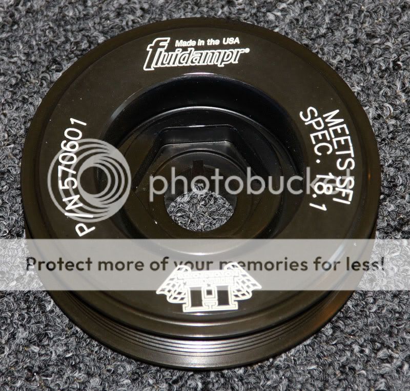
Fluidampr Harmonic Balancer (K Series)
Additional Parts:
Skunk2 Pro K Series Intake Manifold
Bosch Injector Dynamics ID725cc Injectors
Skunk2 70mm Throttle Body
Custom Exhaust Header/Manifold (local builder TBD)
Engine will ship 8/16/10 and build will start immediately.
While the Rover VHPD won't be rebuilt immediately, I do plan to pack & store all the Sport 190 components I remove for future restoration to factory specs. If I ever decide to sell the car, they'll go with it. I promised myself not to do anything that couldn't be reversed, after all this is one of about 50 Sport 190's (very rare).
----------------------------------------------------------------------------------------------------------------------------------------------
Next, I needed a transmission. In order to make life easier, it made sense to use the same transmission the K20 would use. That way, all the existing mounts/mount kits would work. I sourced a 6 speed transmission from an '04 Acura RSX Type S for $800. This is basically the same transmission found in the '02-05 Euro Civic Type R, but it has a longer final drive gear (4.389FD). Actually, the longer FD gear might be better for the higher torque delivered by the K24 (especially in such a light car).

Here's where a major decision had to be made. Which conversion kit/mounts to go with? Since Alan Gourlay has been my mentor from the beginning (Thanks Alan!! You da man!!), my original plan was to follow his Stark build. But after several conversations with my tuner regarding my HP goals, I needed to go with some of the 'higher performance' intake manifolds. The problem was that because the Stark mounts position the engine more forward, these 'higher performance' intake manifolds would most certainly hit the forward bulkhead/firewall. While I could have cut the firewall, I decided that was not the best path (after all, it's a Sport 190).
There was another problem too. Remember the different bolt pattern on the front of the K24 chain case? The Stark front engine mount was designed for the K20, so some serious modification would be needed to make that mount work.
The Link-Up mounts move the engine/trans about an inch further toward the rear of the car, but there will be some 'deeper' cutting of the transmission to adequately clear the rear sub-frame mount on the Lotus. That additional inch opens up a range of 'higher performance' intake manifolds that will most certainly help me reach my power goal. It also straightens out the drive shafts a little more which I'm told reduces heat build-up in the tri-pod joints (plus no need to cut the sub-frame as required for Stark drive shafts). Don't get me wrong... I think the Stark kit and the folks at Stark are 'top shelf'. A GREAT K20 conversion kit. For me, it was about the intake manifold and front engine mount.
Minor Problem: Link-Up mounts are ONLY part of a kit accessible to certified installation shops. Called Geary at EliseParts... no luck. On to PLAN B.
Plan B: Stormin Normin (SELOC) took the Link-Up mount design, made slight improvements through his own experiences, and has a local fabrication shop that makes them up for him at a fraction of the cost ($500). Problem solved.
No so fast... these are just the mounts. Not a kit. What does that mean? No instructions. Little to no support (but a GREAT price). No bolts or associated hardware. Go this route... you're on your own. Not like the professional delivery of Stark's kit and support. But wait, I'm installing a K24. Half of any K20 Conversion Kit I purchase won't work anyway. It was then that I realized I would have to become VERY resourceful for the parts I would need to pull this off.
I ordered the SNS Automotive mounts (Stormin Normin) and they arrived a few weeks later. The bushes were not installed so I dropped them off at the local machine shop and the pressed them in. Tight fit... but they went in nicely. I also had them sandblast them so I could apply a new coat of paint to them.
First things first. I need to cut the corner of the transmission so it will clear the Lotus sub-frame mount. I get an old photo from SNS that indicates where to cut.

Pretty straight forward. I grab my trusty hack saw and go to town. (Previously, I was a hand model... but was not 'master of my domain'. I even lost a contest once)

I love a perfect cut! Wait... WTF!!!

I'm pretty sure that's going to leak some tranny fluid. Wow! It was then I realized... "Welcome to the world of DIY!" Time for a cold beer and some reflection.
The next day, I split the transmission case... rinsed all the shavings/filings out... and headed off to my specialty welder. $40 and he plugged my hole (no comments guys). It was then that I felt... well... resourceful. An unexpected issue pops up... deal with it. Solve the problem.

Little bit of paint... and we're back in business. In fact, now I'll have a ton of room.

I don't fault SNS. I made the cut without talking to others and getting consensus. A 'teachable moment' as they say. I pretty much get a grin on my face when I think back on my surprise when I did that.
I re-assembled the transmission and started to fit the new SNS mounts.

I'll have to say, the SNS Mounts fit PERFECT. Very precise fabrication. Very happy with them thus far. I had to get resourceful when it came to the linkage assembly sourcing the ball end joints, threaded rod, and stainless steel hardware from http://www.fastenal.com (great source for hardware). The existing shift cables will be reused and will connect directly to the rocker arms.

Linkage works smoothly with no binding. I also installed a new clutch slave cylinder, drive shaft seals, boot and throw-out bearing.

-----------------------------------------------------------------------------------------------------------------------------------------------
While I wait for the engine components to arrive from Endyn Racing, I decided I may as well pull the front clam. After all, I'll need to replace the Elise OEM radiator. Why replace the radiator?... I'm glad you asked.
The Acura K Series engines (Honda's too... one and the same) have a cooling system that operates at much higher pressures than the Rover K Series engines do. This increased pressure can blow the pressure plugs out of the OEM radiator, resulting in the loss of your engine coolant.
Notice all the dusty dirt and broken driving light. I took a short cut (or long cut) at 80mph around Turn 3 @ BIR. Woo Hoo!! The dry cleaners are still trying to get the stains out of my racing suit.
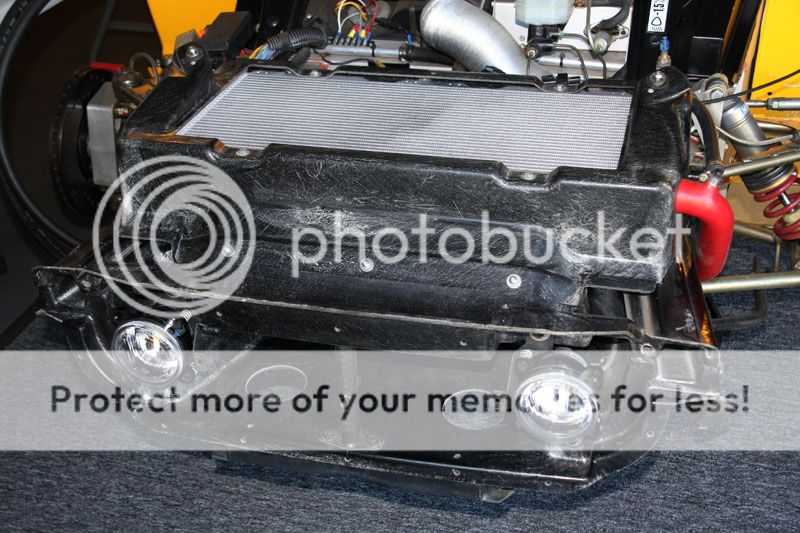
OEM Radiator Removed.

It is highly recommended that the radiator be replaced with a High Pressure Extra Capacity Aluminum Radiator supplied by my friends at Elise-Shop. I opted to install two fans, vs only one in the OE configuration.
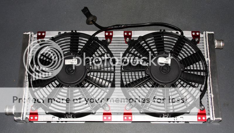
Here is the new radiator installed. I also took the opportunity to replace the two front driving lights. Elise-Shop was kind enough to include plastic light shields that take the brunt of the rock chips incurred on track.
After siphoning the remaining fuel from the OE 8 gallon tank, I dropped the fuel tank as we'll need to replace the OE in-tank fuel pump. Why? You guessed it... because the Acura K Series engines/injectors like to operate at a higher fuel pressures.
Note: Another option is to leave the OE pump and install a surge tank (a swirl pot) in the engine bay with a secondary pump. Aside from the arguable safety issues created by that approach, I need the engine bay real estate for more critical performance components (i.e. laminova oil cooling system & remote oil filter).
Many take this 'swirl pot' approach because there really hasn't been a quality manufactured in-tank replacement pump solution... until now. Read on...
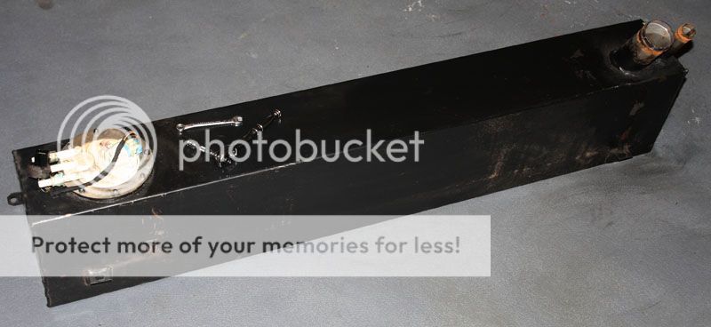
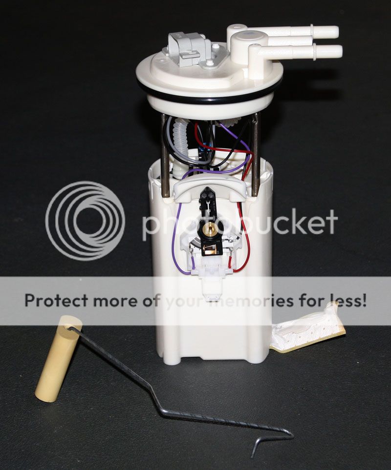
OE in-tank pump removed.
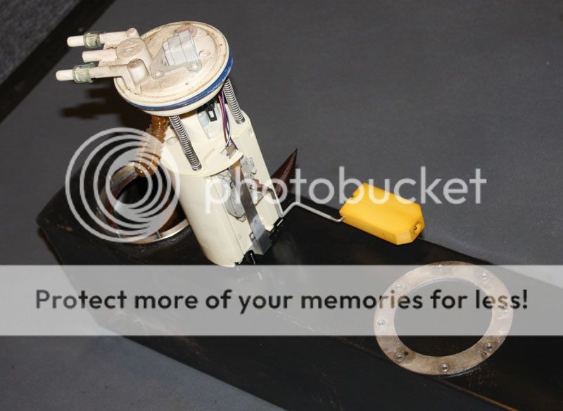
Here is the newly released high pressure in-tank fuel pump designed to replace the Lotus OE pump. This is actually the first one shipped from Yvo @ Elise-Shop (actually the first prototype). Now there are probably a few folks out there that think this idea is not new (and its not), but what is new is that it is not a hodge-podge assembly of replaced parts on the OE pump, but rather a completely re-designed piece of performance equipment designed (and factory manufactured) specifically for Lotus engine swaps. Elise-Shop now offers many new custom parts to assist DIY customers.
http://www.elise-shop.com Talk to Yvo. I can't begin to tell you how much help he has been. Thanks Yvo!!
Comparison to OE pump
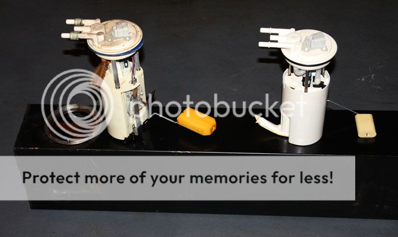
New pump fitted and fuel tank re-installed
I'm going to need to make room for all the engine components and parts that will arrive this week so a quick trip to Lowes for some wood and I'll box up the OEM Rover 1.8L and 5 spd trans to store in my barn (in case I ever want to restore the car to OEM specs). I kind of felt like I was making a coffin for a dead engine.

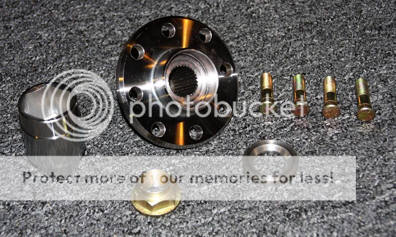
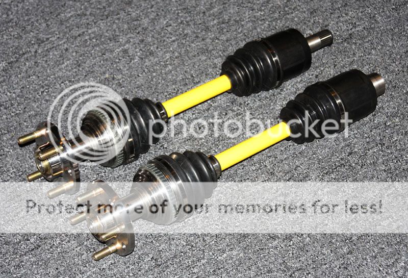
The first items to arrive were my OEM Acura drive shafts (RSX Type S) and the kit necessary to convert them for use with the Lotus Elise S1 Hub Carriers/Uprights (appropriate length axles and custom wheel hubs).
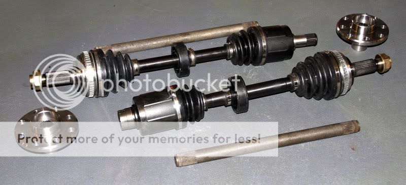
All that will be used from the new Acura drive shafts is the inner and outer joints/boots. A custom length drive shaft and custom fabricated wheel hub (from a UK supplier) will complete the custom drive shaft assembly.
Notice the size difference between the OEM Lotus Joints and the OEM Acura Joints. Although some kits make use of the Lotus OEM Outer CV joints, it's no wonder they're prone to failure under extreme performance use at much higher HP delivered by the Acura K Series engines.

I will have to custom fabricate a speedo sensor bracket to accommodate the larger Acura CV joint... but then who needs a speedometer on the race track? :driving:
So what I need to do is rebuild the drive shaft and fit the new axle.

There was a slight problem with the custom hubs working properly with Honda CV joint housing, so some additional machine work was necessary. The first problem was that when the Honda spline nut was fitted, the 36mm socket would not fit over the nut without hitting the hub flange (centers the wheel for lugs). The solution was to shave a little off the inside of the flange and turn down the socket a little. Now it works fine (and the flange is still thicker than the OE hub flange).
Second problem was where the Honda CV joint mated up against the inner Lotus wheel bearing. While I could have turned down the Honda CV housing a little, I knew this part would be eventually replaced and I'd have to machine it again. I had my machinist make me a custom stainless steel spacer that sandwiches between the CV joint housing and the Lotus bearing. Should work perfect.
New drive shafts fully assembled and ready to go...
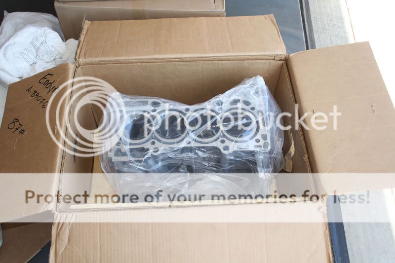
Finally.... my engine arrives back from Endyn Racing (Ft. Worth, TX). Woo Hoo!! First thing... a quick inventory of parts. (Man I love it when UPS comes screaming down the street!!)
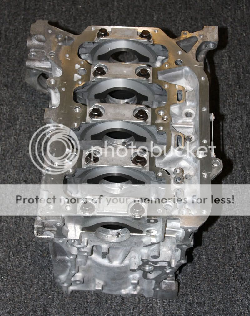
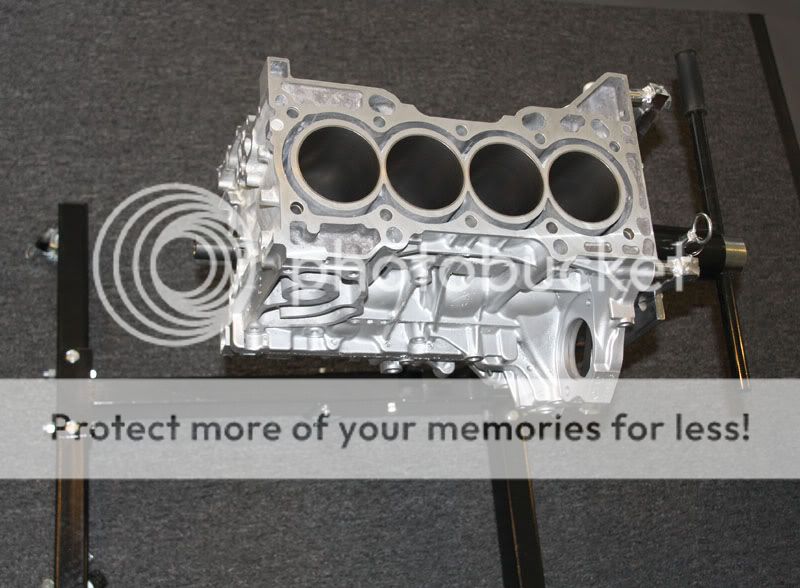
Machined Block - Deck Block / Line Hone Main Journal / Bored & Hone to 87.5mm (with deck plate)
Cylinder Head - Full Race Modifications (this thing is made to FLOW... baby!)

Eibach Dual Valve Springs / Chromoly Retainers
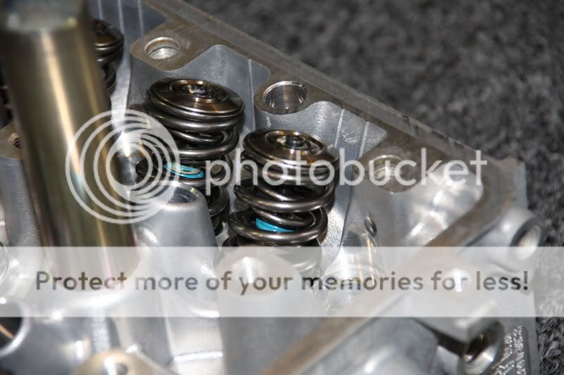
Black Nitride Coated Valves (+1mm Intake Valves with Seats)
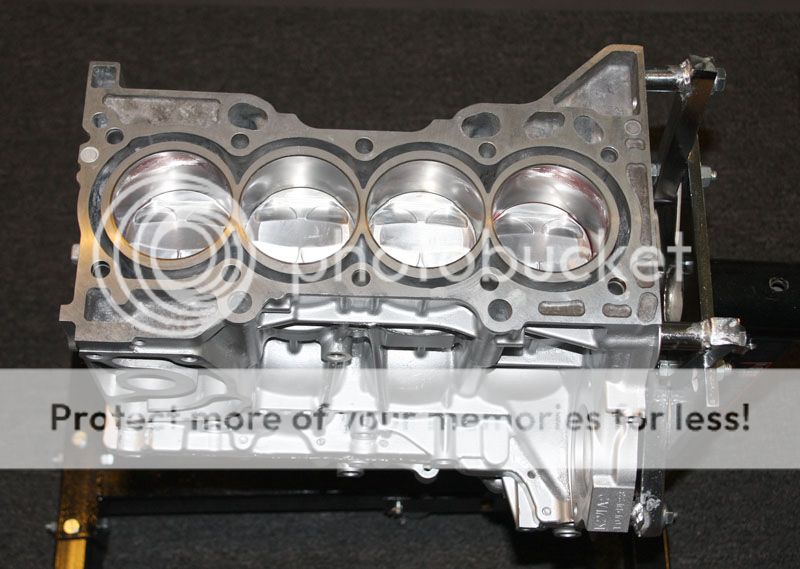
Open up and say "Ahhhhhh"!
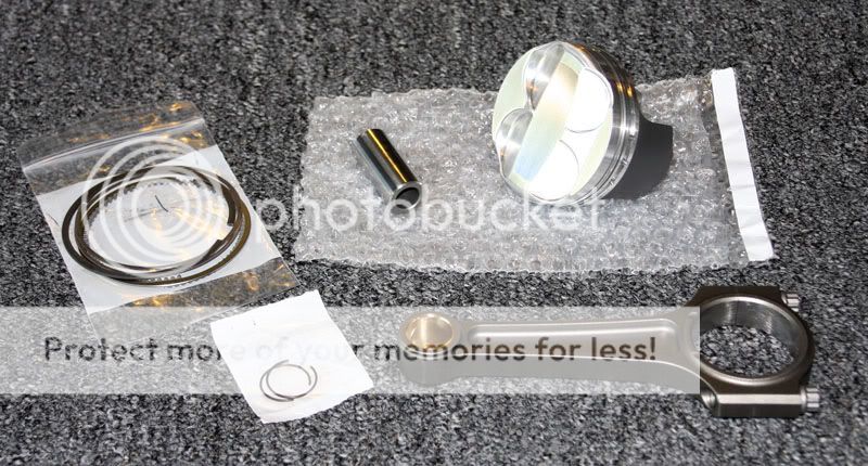
Custom Endyn Roller Wave Pistons - 87.5mm 12.5:1 Compression / Coated Skirts
Custom Crower MaxiLite Billet Connecting Rods (Not to be confused with Brian Crower rods)

Modified K20 Oil Pump / Port & Polished (note machined area for K24A2 application - more on that during assembly)
Fluidampr Harmonic Balancer
Toda Chain Tensioner
Custom Endyn Stage 2 Cams will arrive shortly, but I'm ready to start building this bad boy!
Block shipped with both halves of block together, so the first order of business is removal of the lower block assembly. We'll need to install the crankshaft before we can bolt the block to the engine stand.
Install the four oil squirters first.
I had Endyn prefit all bearings and rings to performance specs, so its important to get each bearing in its appropriate journal.
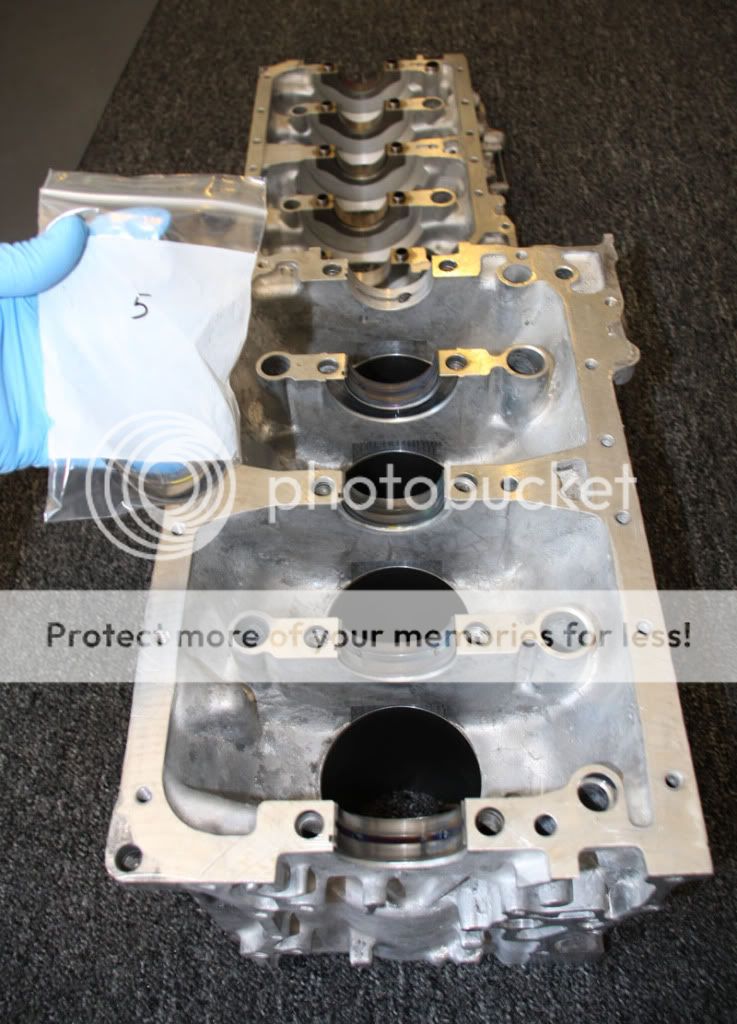
Once the bearing halves are installed, generously coat each with a thick coat of assembly lube. Don't forget the thrust bearings. :rolleyes:
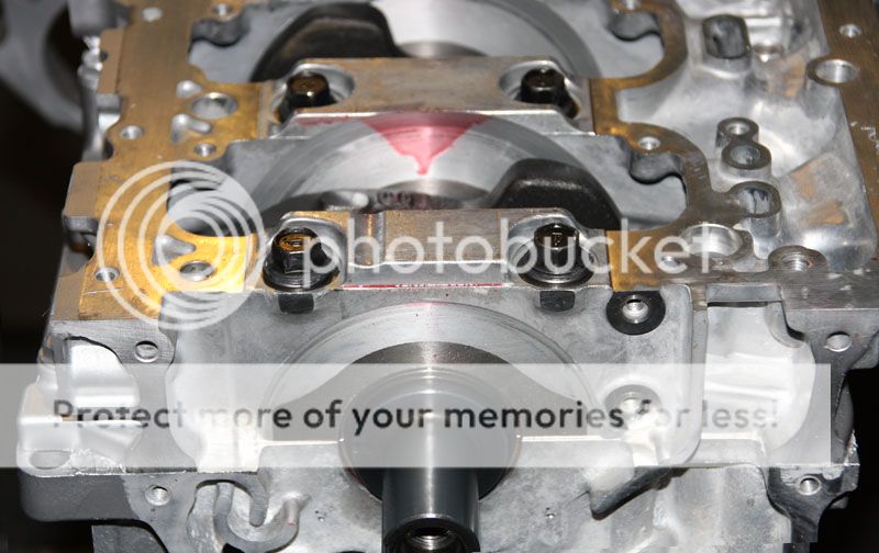
Lower the crankshaft 'very carefully' on to the lubricated bearing halves. Then lube the bearing halves on the lower block assembly.
The lower block will require HondaBond gasket sealant, and this stuff dries pretty quick. I suggest before applying the HondaBond, have all your bolts ready to go and your Torque Wrench adjusted for the main caps.
It's important to replace the Main Bearing Cap bolts with brand new ones. You'll also want to use a quality moly lubricant (i.e. ARP) on the threads and between the bolt head and washer. This ensures proper torque is achieved with minimal resistance. So have your ARP moly lube ready as well. Lastly, clean the HondaBond areas with 3M Adhesive Remover to get any oil residue off the mating surfaces.
Ready... set... go..... Apply the HondaBond to areas as indicated in the engine manual. Smooth out with your finger and assemble the block halves together.
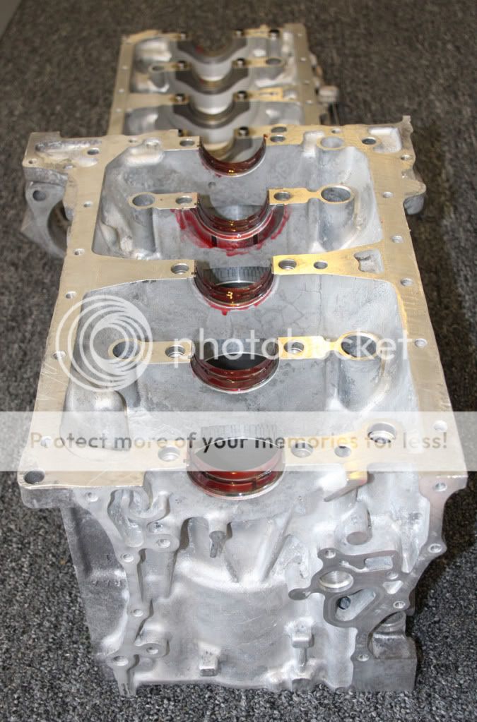
Apply moly lube to the main bolts and torque to specification in the sequence indicated in the engine manual. Once torqued, go back and check them again.
Your not done torquing these yet. Start again in the proper sequence and turn each main bolt an additional 56 degrees (as shown in the manual). Now you can install the remaining bolts around the perimeter of the lower block and torque to spec.
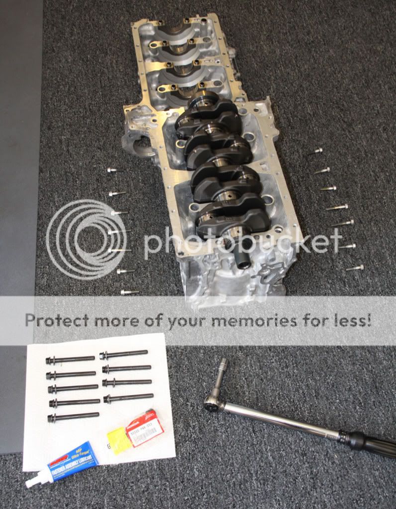
And the crank spins as smooooooth as butter. Let's put it on the engine stand and assemble the pistons, rings and rods.
Again, since Endyn has already set the ring end gaps and honed the rod journals, we just need to assemble (again per the manual). Exception: The piston pins on the Crower Rods are floating pins, so no need to heat the piston and press in. Just apply a little assembly lube to the wrist pin, install the snap ring, and your good to go. Note: It is important to ascertain if the rods need to face a certain direction. Mine needed the journal tangs toward the exhaust side of the piston, but check with your manufacturer for your application.
Install your piston rings with end gaps facing angles as indicated in the manual and your ready to install in the cylinders.
Important Note: Invest in Wiseco Tapered Ring Compressor sized for your specific application. These install the pistons effortlessly! The universal 'crank-to-compress' ring compressors are RISKY and can damage your cylinders, rings and pistons pretty easily.
Identify the first cylinder (cylinder 1-4 front to back) and rotate the crankshaft so the journal for that cylinder is at BDC (bottom dead center). This will help ensure the rod bolt don't contact the polished journal and score/scratch it.
Use plenty of assembly lube on the piston, the cylinder, and the tapered ring compressor. Install the bearing on the connecting rod and apply more assembly lube.
Ensure the piston is facing the correct direction (valve indentations aligned with valve sizes). The larger piston indentations (intake valve indentations) should be on the same side of the engine as the intake manifold. The smaller indentations go toward the exhaust side of the engine.
Place the tapered ring compressor on the cylinder (ensuring the piston/rod combination is for that cylinder - they're matched). Lower the piston/rod assembly carefully into the ring compressor. LIGHTLY tap the piston down into the cylinder with the wooden/rubber end of a 'LIGHT' mallet.
Once the rings have cleared the block deck, remove the ring compressor and set aside. Continue lightly tapping the piston toward the bottom of the cylinder. Reach underneath and guide the rod onto the crank journal (preventing the rod bolts from touching the journal surface.
Rotate the engine (bottom up) and install the rod cap (with lubricated bearing half). Install the rod bolts using ARP moly lube. The lube should be used both on the threads and the underside of the bolt cap. This allows for proper pre-load while torquing these bolts (minimal metal to metal resistance for accurate torque readings). Torque to rod manufacturer specifications (which may be different from OE torque specs indicated in the Helms manual).
Repeat process for remaining cylinders. Since I was building this by myself, I couldn't really take photos of each step of that process. Here is the finished installation of pistons/rods. You should be able to turn the crank without binding, but understand it will get more resistant to turn as you install more pistons.
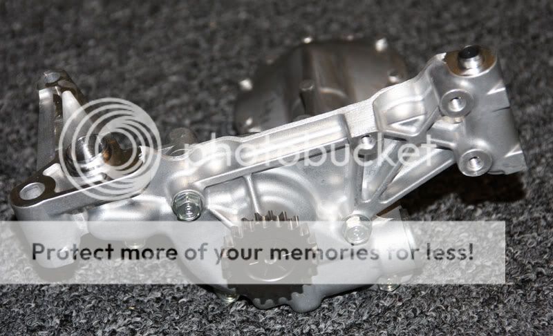
The next step is to install the oil pump. I've replaced the bulky and heavy K24A2 oil pump with a modified K20A2 oil pump. It had to be modified to work with K24A2. Note the lower block bolts are not flush (as on the K20A2), so they prevent the K20 pump from directly bolting on.
The solution involves machining some unnecessary aluminum off the K20 oil pump so that it straddles the K24 lower block bolts. Endyn performed this modification and also ported/polished the pump for improved flow.

A small oil port (used on the OE K24 pump also needs to be plugged to prevent loss of vital oil pressure. Once again, Endyn plugged for me.

Lastly, I installed a K20A2 baffle (throwing the old K24 baffle in the trash with the K24 pump).

A new K20A2 oil pump chain and guide must also be replaced (as part of the oil pump conversion). I also opted to replace the chain tensioner as well.

The next step is installation of the cylinder head. First, I installed the new ARP head studs, finger tight but fully seated. Don't forget the two dowel pins that center the gasket and head precisely over the cylinders (not shown in that photo... but installed).

Head, valve train, and new Endyn Stage 2 cams installed.
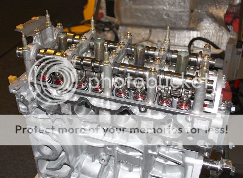
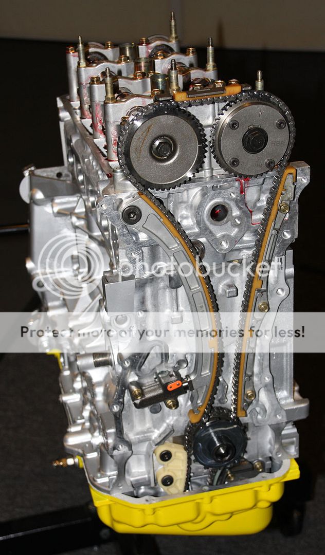
Installed cam gears and new timing chain / Toda chain tensioner.
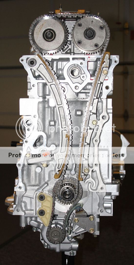
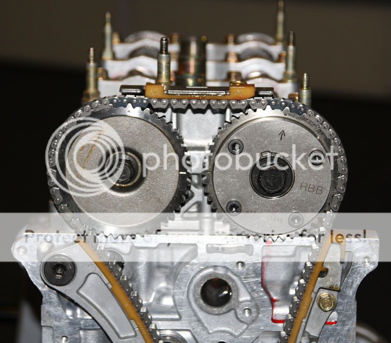
Align arrows on crankshaft. Note dark gray chain link aligned with crank gear dimple mark.

Align cam gears. Note cam gear marks are aligned and dark gray chain links are aligned with dimples.
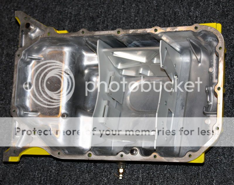
The next step was to install the oil pan with Clockwise Motion oil sump baffle installed. Note that I have opted to use an aluminum K20 oil pan. While I could use the K24 steel oil pan, the sump baffle wouldn't work with that pan. I also had to purchase longer bolts as the aluminum pan has a thicker outside edge than the thin steel pan.
Install Chain Case
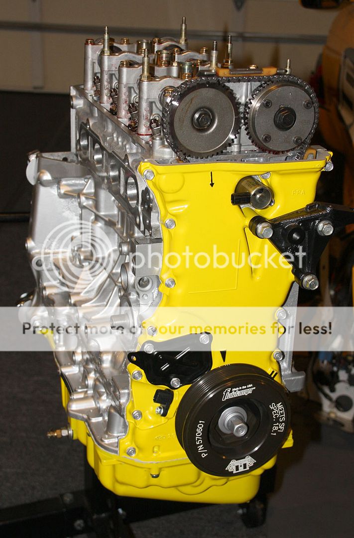
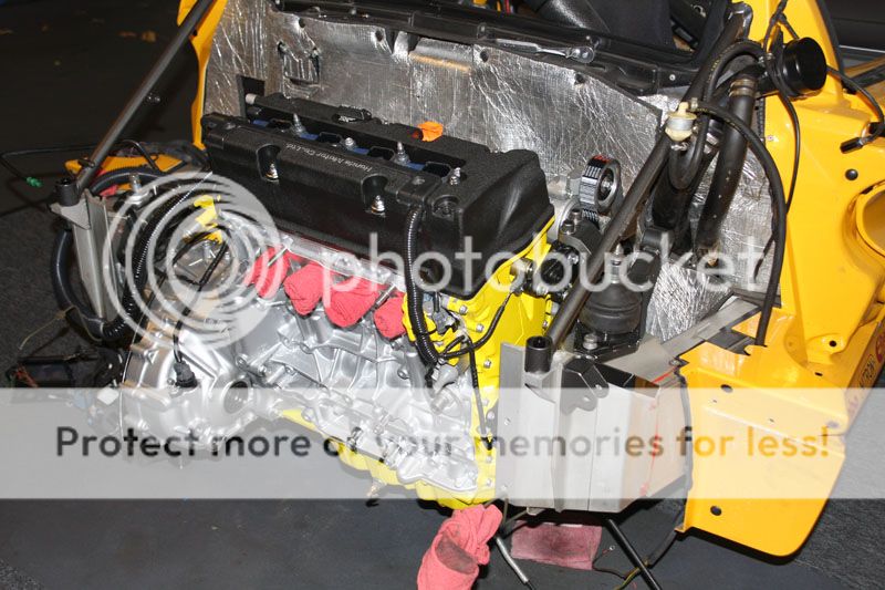
Install remaining engine components (new water pump, Fluidampr Harmonic Balancer, etc)
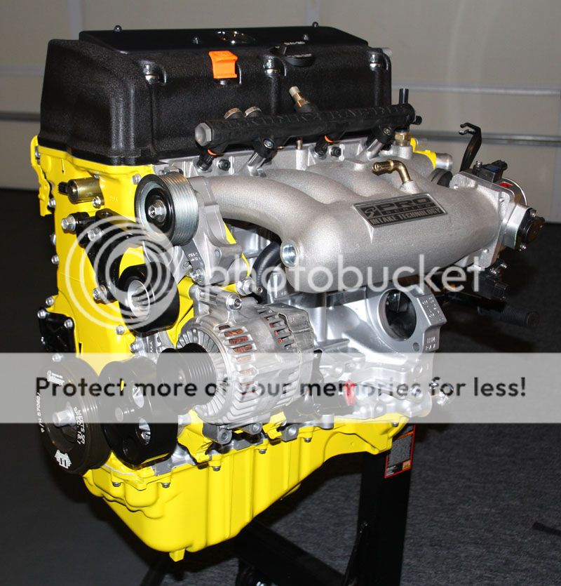
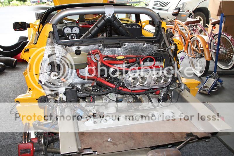
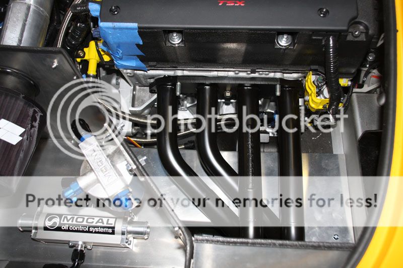
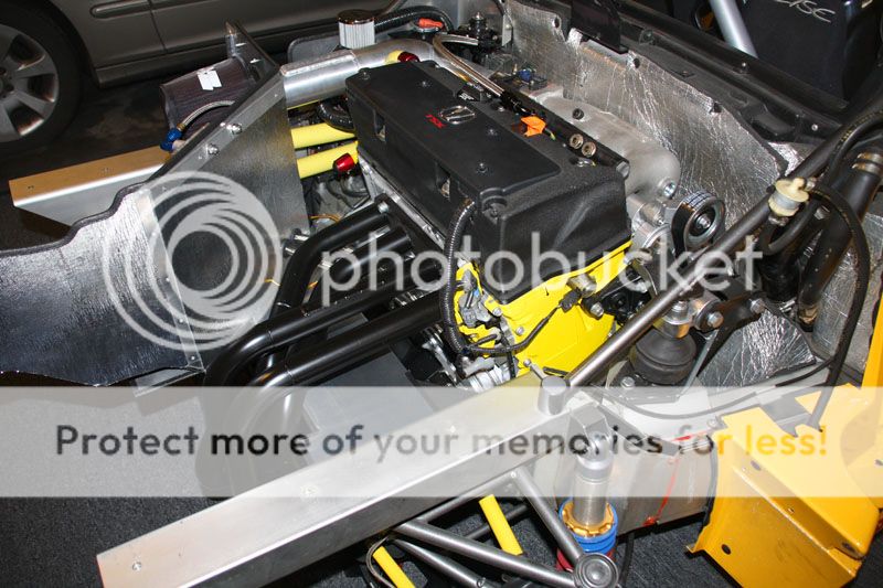
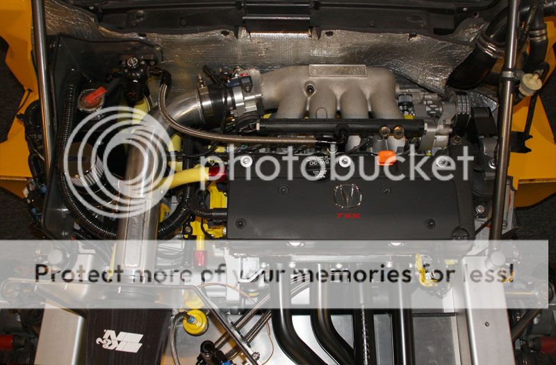
Skunk2 Pro K Series manifold with Skunk2 70mm Throttle Body, Skunk2 Composite Fuel Rail, and Bosch Injector Dynamics ID725cc Injectors.

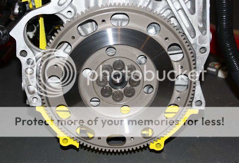
Hoisted the new engine off the build stand so that I could install the Exeedy lightened flywheel, clutch and transmission assembly. I didn't feel the need to go full race on the clutch, as this is not a drag race car that I dump the clutch in. The car also only weighs in at 1600 lbs, nearly half the weight of a factory Acura RSX/TSX. I just need acceleration in the straightaways from 3rd-6th gear. This was a judgment call, so if I underestimated... I'll put another one in. I'm pretty easy on clutches though, as I don't beat on the car that much.
I also opted not to install an LSD. I spoke with several Elise owners who had them installed. While most liked them, they felt they were most beneficial for autocross/solo track driving or in 2nd gear turns (hair pins). On faster 3rd-6th gear tracks (long sweeping turns), it didn't seem to provide much benefit (unless you like sliding/drifting). Not a hindrance... just not as much benefit on longer road race tracks. Again... a judgment call. If I have traction issues, I'll re-evaluate.
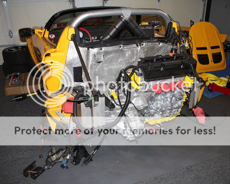
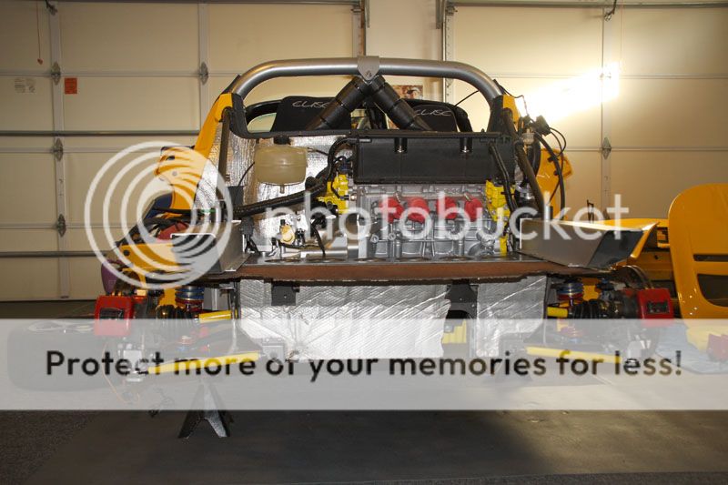
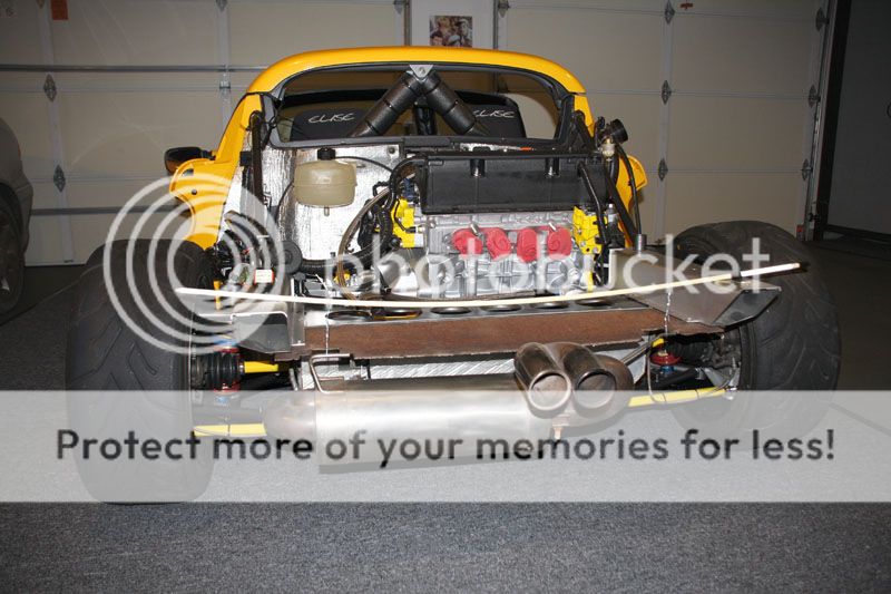
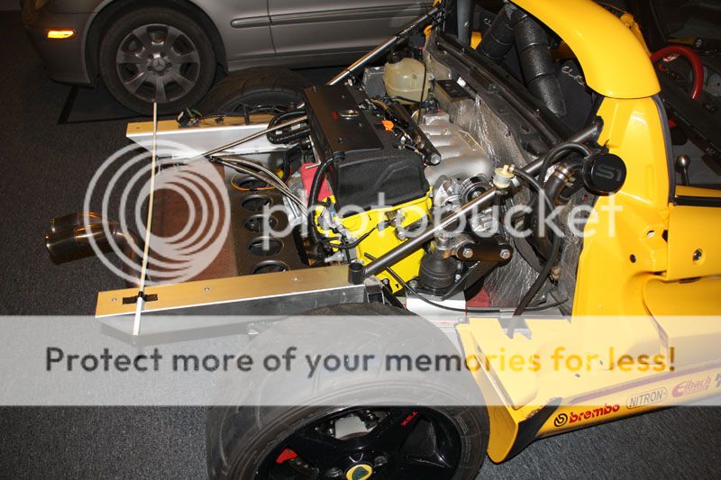
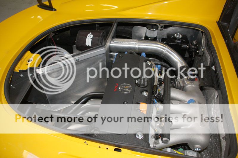
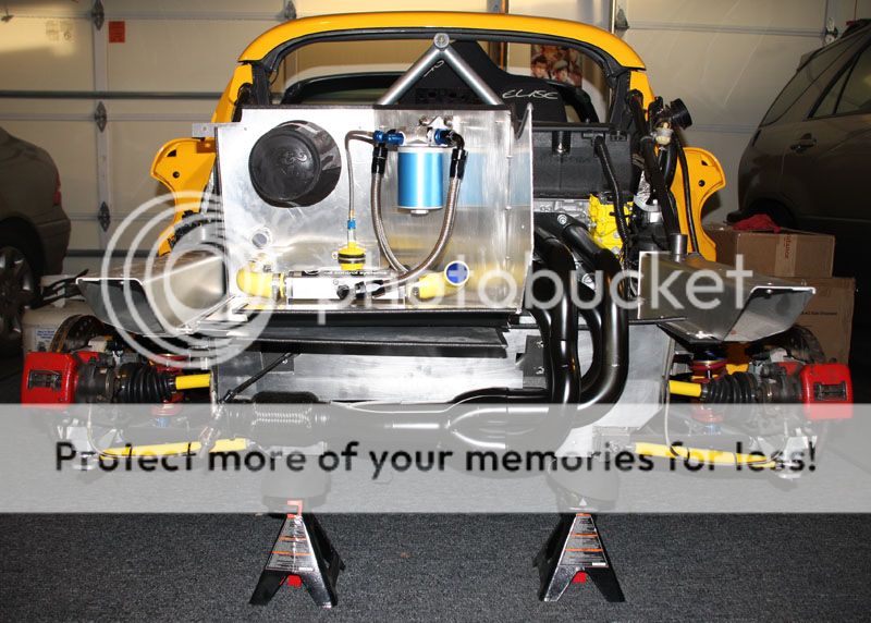
OK... time to fit the engine in. Since this was going to be like putting a watermelon in your lunchbox, I removed the intake manifold for more room (also not to scratch). I lined the aluminum chassis rails with towels to minimize scratching, and also because I'm installing this by myself... solo.
I removed the gearbox mount (n/s mount) so it would clear the chassis rail mount. Positioning the engine/gearbox at about a 35-45 degree angle (gearbox down), I dropped it in and slowly. I positioned my floor jack under the gearbox and began to use it to level out the engine as it dropped in. Once pretty close to level, I attached the right side/front engine mount (o/s mount). Raising the gearbox up a little more, I reinstalled and connected the gearbox mount to the chassis rail mount. Surprisingly, it went in pretty easily without issue or scratches.

After leveling the engine and adjusting lateral placement, it's time to install the lower anti-rotational mounts included with the SNS mount kit. I also need to do some custom machine work to the front engine mount (not the SNS mount, but the OE Lotus mount/spacer it bolts to). Just shave a little aluminum off to make the engine sit perfectly level.
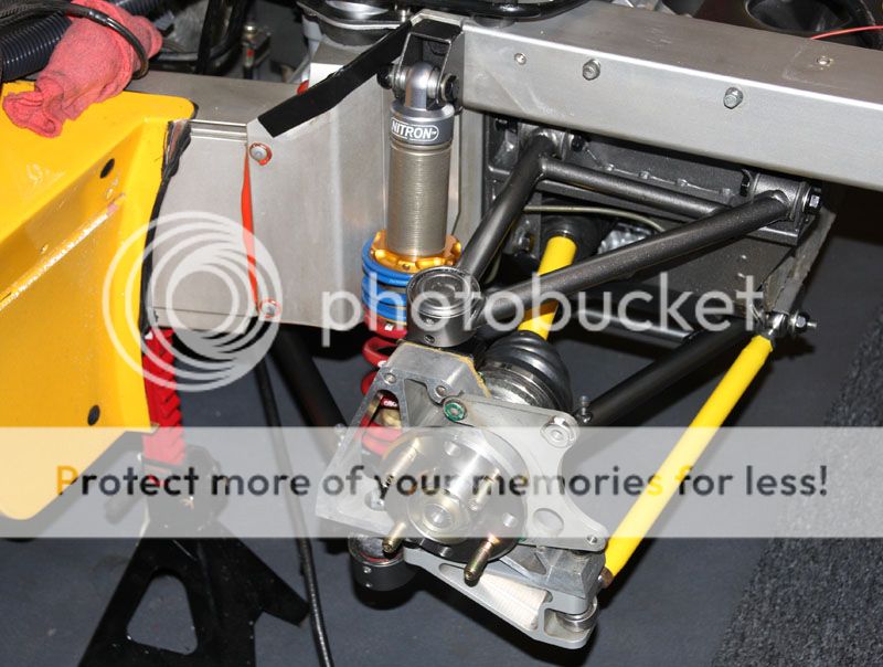
The next step was to re-install the rear Lotus subframe, a structural component attached to rear chassis rails that provides attachment for the rear suspension components. I also took this opportunity to replace the ball joints. The Nylatron bushings are still pretty new as this car only has about 5k miles on it.
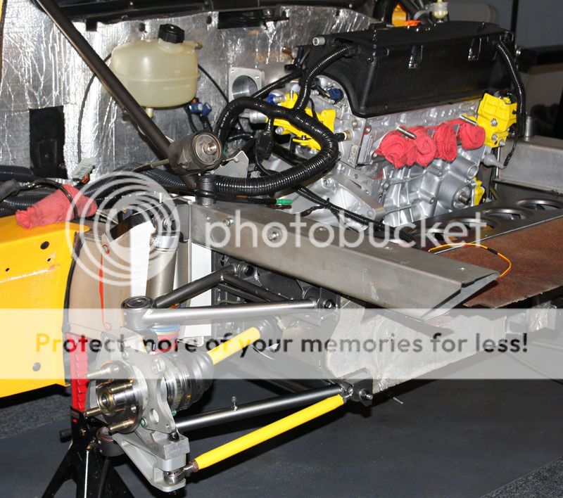
The new 'shorter' drive shaft assembly has been fitted. Fits perfect! Note the distance between the axle and the sub-frame (approximately 8-10mm / 1/4 - 5/16"). Some of the other kits place the engine about an inch (50mm) further forward, so some sub-frame cutting/grinding is required to make room for the more extreme angle of the axle. This increased angle can cause a little more heat build-up in the joints (due to increased friction). According to some, this is not a huge issue for street use, but under extreme track conditions it could be a potential problem.
This of course will not be an issue with the SNS Automotive Mounts and Martyn Tinker drive shafts. They installed flawlessly without issue.
Another angle...

After properly torquing suspension components, the brake disc and caliper is re-installed.
After modifying the right lower A-frame (moved the cross-member out 2" or 50mm) to clear the front of the K20 aluminum oil pan, I re-installed the right-side suspension components. Drive shafts spin smoothly and tight without resistance. Filled the transmission with two quarts of Redline MTL. No leaks... good to go.
Important Note: It is important to let the new drive shaft joints break-in for 1,000 miles or so before subjecting them to extreme stress and temperatures. New joints are tight and the increased angles in a Lotus mid-engine configuration don't help.
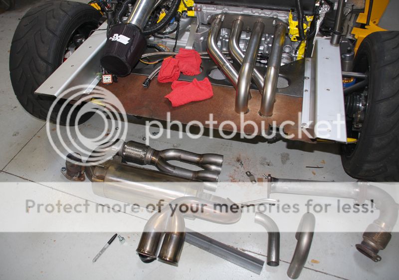
The next step is to get the car into the shop for custom exhaust header fabrication. The shop I've selected will also build some custom sheet metal in the engine bay for mounting engine peripheral components (i.e. Catch Can, Laminova Oil Cooler, Remote Canton Oil Filter, & Fuel Pressure Regulator and Filter).
Since the car won't fit into their schedule for a couple weeks, I'll take this opportunity to finalize the integration of the K20/24 engine wire harness into the Lotus electrical system (via a new Acura PRB ECU with Hondata K-Pro). I sourced a new female E connector and male C101 connector with new pins.
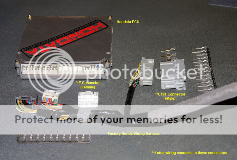
Alan Gourlay graciously shared his conversion schematic diagrams with me that clearly showed all the modifications necessary. After installing pigtail wires on the new connectors, I made the proper connections to the Lotus electrical system. Thanks Alan! His drawings were extremely helpful (and necessary), as this can be probably the biggest challenge of the conversion..

Though it's a little difficult to see, you can see that I've temporarily hung the ECU (and other associated electrical) from the left sub-frame support. These will mount to an aluminum panel that will be custom fabricated at the performance shop. I'll take close-ups of that once completed. On the inside of the custom panel will set the fuel pressure regulator. Electrical conversion is pretty much complete.

From this angle you can see that I've temporarily suspended the Lotus after-market stainless steel exhaust system so that the header fabricator can build to it, maintaining the original look of the car's exhaust from the rear. I had to temporarily suspend it with a fiberglass rod because it's normally mounted to the rear clam body assembly.
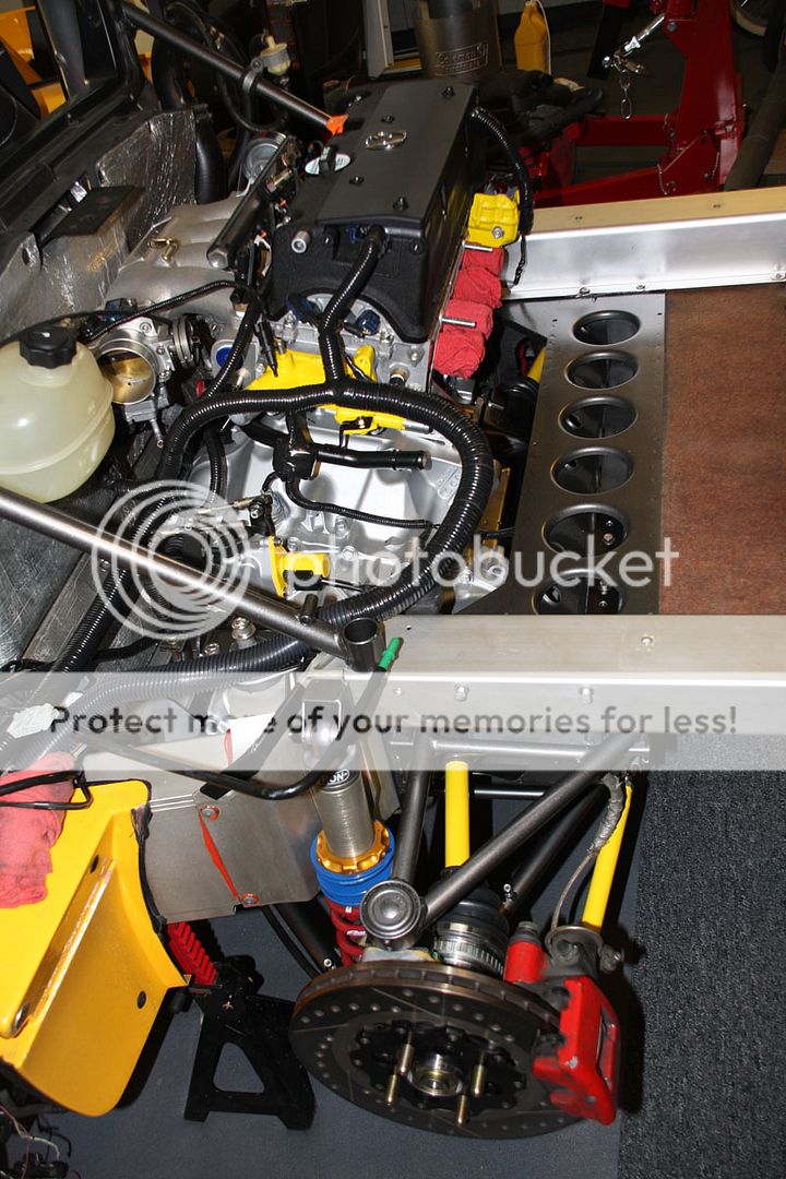
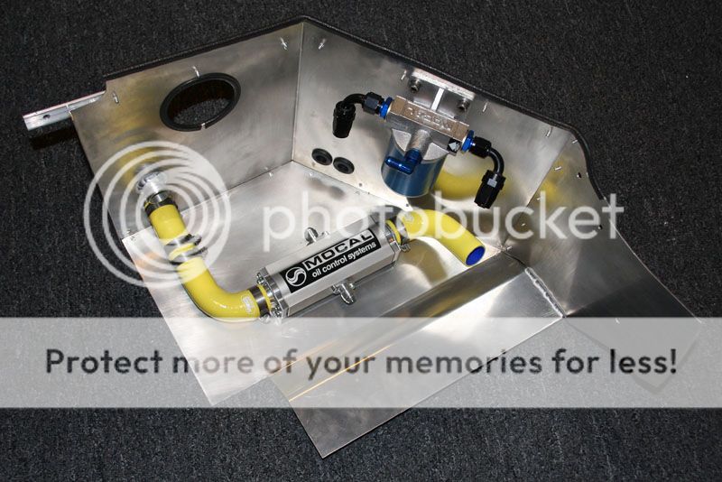
Here you can see that I've started the plumbing phase. Note the Mocal Oil Take-Off sandwich plate and 8AN stainless steel braided hose. These will feed into the remote Canton oil filter (replaceable cartridge type) and Mocal Laminova Water-fed Oil Cooler on the rear deck (after some custom sheet metal of course).

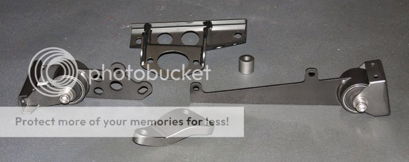
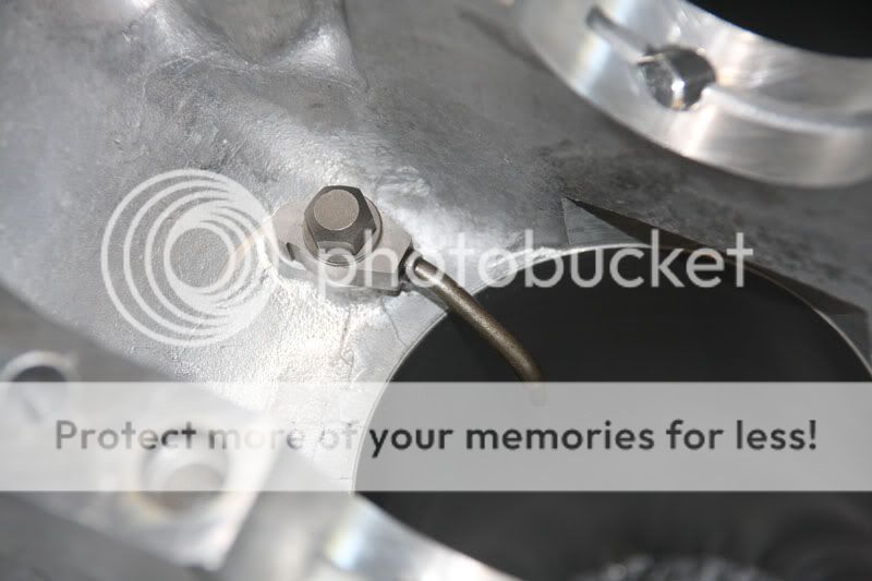
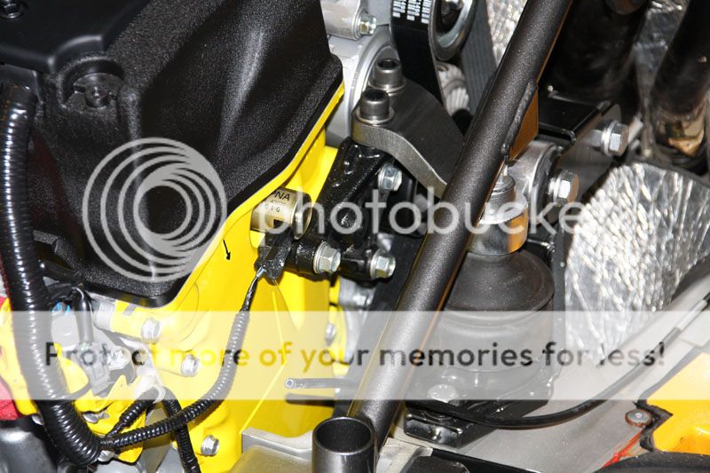
For those interested, here is a close-up of the adapted Lotus/Acura engine mount (using the SNS custom adapter mount). Used a OE Honda CRV chain case engine mount to adapt the SNS K20 mount to the K24 chain case.
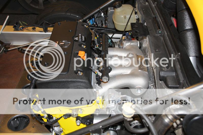
Here you can see why an RBC manifold simply won't work very well on a Lotus application. The RBC sits 1/2" further off the head than the Skunk2 Pro K-Series manifold (10"). While a little hard to see, it's less than 1/4" off the firewall, but the firewall has a good 1/2" of spongy rubber on it so contact due to a little torque rotation won't be an issue.
Next stop... header fabrication shop... then the sheet metal shop.
Found a six-speed gear knob for the Honda S2000... and it's even my favorite color... Yellow. I will nee to change that aluminum shift gate though since this is no longer a five speed.
Trailered the car over to Full Blown Motorsports in Apple Valley, MN. http://www.fullblownmotorsports.net
They specialize in custom fabrication manifolds and turbo set-ups. Although I'm going normally aspirated, their reputation for custom design & quality fabrication is unmatched.

Their shop area was most impressive and the stable of performance cars reassured me I was definitely in the right place. LJ was great and made room for the car immediately, helping me keep on schedule. Thanks LJ!!
While I dropped the car off a couple days ago, you can see that Chuck didn't waste any time getting started on both exhaust header and cold air intake manifold.

While many exhaust manifolds will drop straight down (preserving the boot/trunk space), our design flows over the top for less restriction, critical on a normally aspirated engines. It also keeps the manifold heat away from tripod/cv joint boots, which can be a real issue on the track.

The plan is to split the rear boot area equally, with custom heat shielding in between the header on the right and the cold air intake area on the left (along with laminova oil cooler and remote oil filter).
Finished Welding
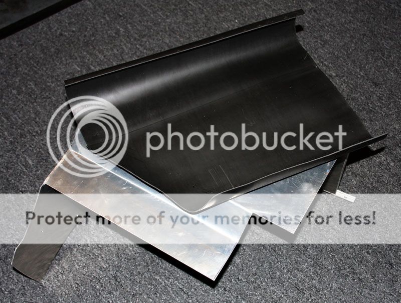
We put the clam shell back on to check fitment and measure for all the custom sheet metal aluminum that will compartmentalize the engine bay (heat/cooling management).


Early look at strategy to effectively manage heat ventilation and cold air zone compartment (for air intake, laminova oil cooler, and remote oil filter).

We'll vent engine bay heat from here (via o/s air scoop/vent).

Just got back from vacation in Key West and I'll have to say, Full Blown has done an incredible job.
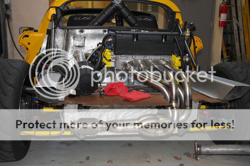
The custom fabricated exhaust header has been ceramic coated & powder coated to satin black. The ceramic coating reduces radiated heat by 70% (no need for exhaust header wrap).
From this angle, you can see a custom sheet metal baffle that funnels hot air down and out the back of the car. Full Blown also added a signature plate to their custom work. Great job guys!!

In addition to the ceramic coating, I'll add some heat barrier on the exterior of the cool air box to minimize heat transduction. I decided to leave the custom Cold Air Intake a natural brushed aluminum.
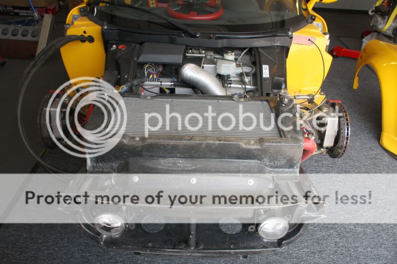
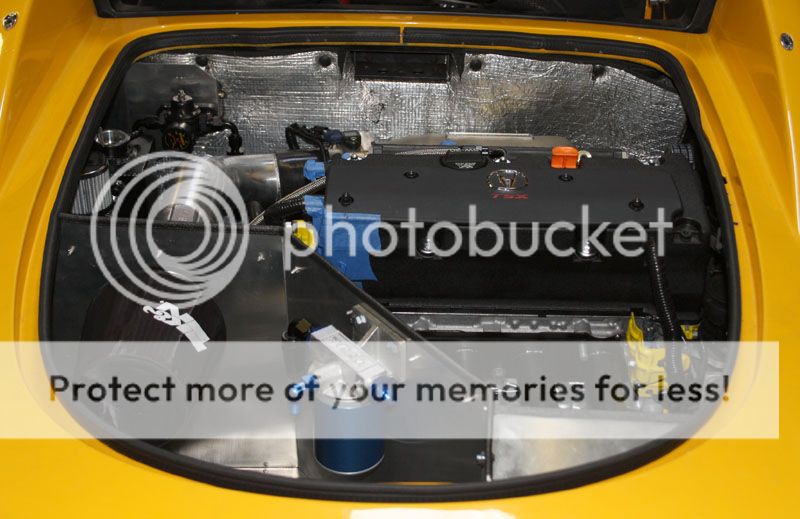
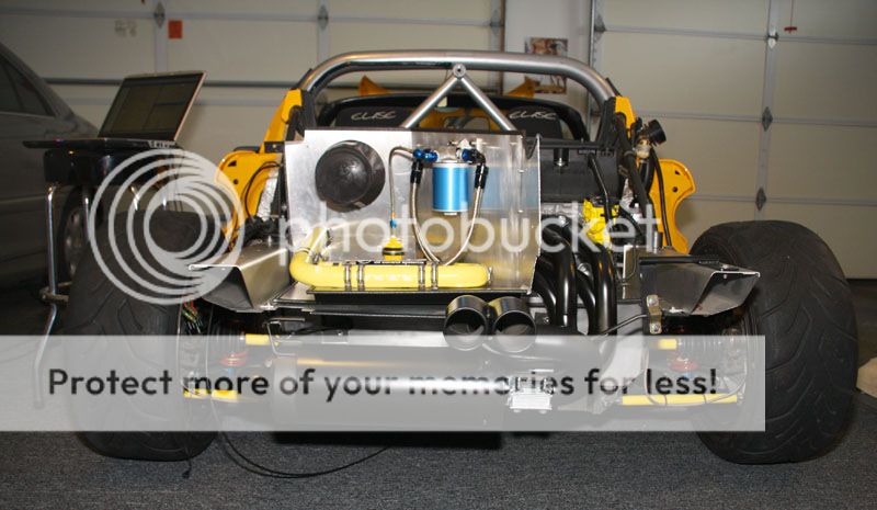
Here you can see the remote oil filter, laminova cooler, and K&N dual air filter system inside the cool zone. Once I get the car back to my garage next week, I'll start the final plumbing.

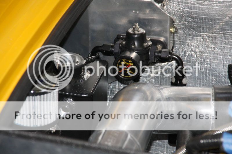
Here you can see the custom sheet metal mounting plate. While you can see the oil catch can, header/expansion tank and fuel pump regulator, you can't see the Hondata ECU and other associated electrics mounted on the opposite side. Once the clam is back off, I'll take a couple pictures.
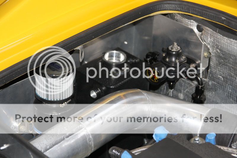
A little more close-up of the K-Tuned FPR & Canton's Aluminum Expansion Tank and Oil Catch Can (powder coated in black satin).
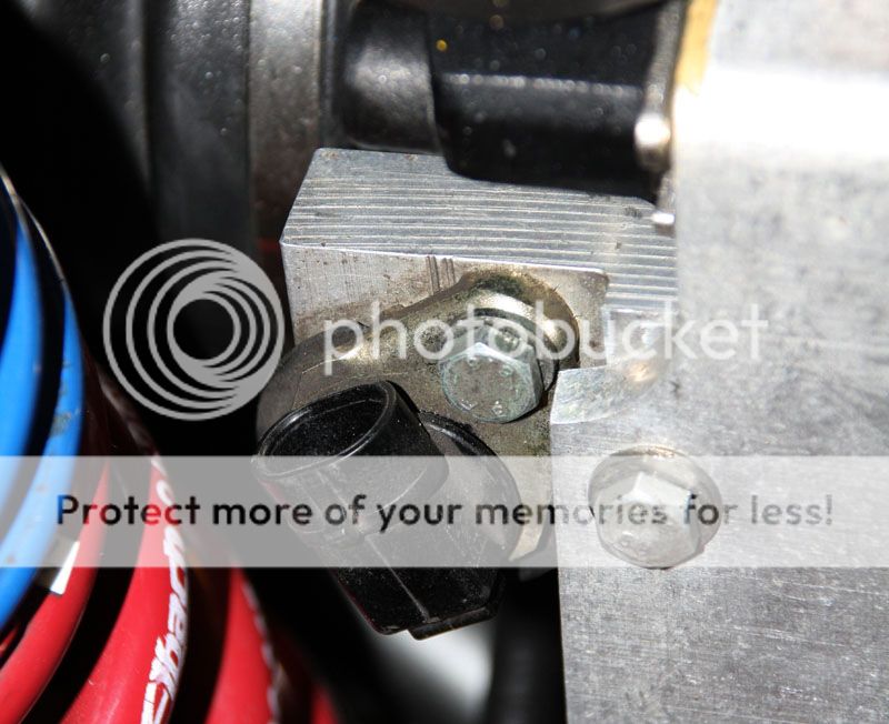
After trailering the car back to my home garage, I removed the rear clam to begin tidying things up a bit and finishing off the plumbing (fuel, oil cooling, coolant hoses). One thing I did take immediate note of was the custom milwork Full Blown Motorsports did on my left rear wheel speed sensor (speedometer signal). If you recall, the outer CV joints are now Acura (with a larger diameter/speedo ring), so modification was necessary to reposition the sensor.
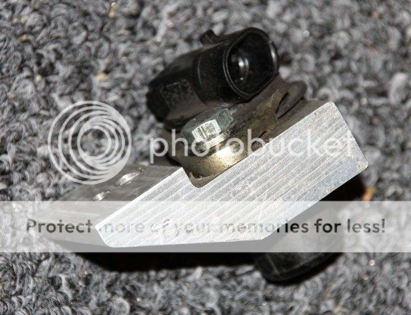
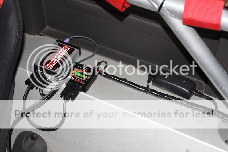
Chuck shaved a little off and drilled/tapped a new mounting point. Should work great, although I'm not sure how accurate it will be. Not to worry though, I'm installing a Traqmate GPS data logger as part of this conversion, which will track exact speed for comparison.

Next I removed the 'cool zone' box to mount the Mocal Laminova Oil Cooler, Remote Oil Filter, and Oil Pressure Sender. Note that Chuck welded in aluminum sleeves for the radiator return coolant to the oil cooler.
I ordered some 3/32" Neoprene rubber to contact cement to the bottom of the 'cool zone' box and other aluminum panels to ensure minimized rattling. In effect, its a rubber gasket sandwiched in between metal to metal surfaces. I also installed some heat shielding around the box.
After installing all the new custom Samco silicone hoses and stainless steel braid, I reinstalled the box. Note the custom sheet metal below. Looks really clean. Great job Chuck/Full Blown!
Here you can see where we mounted the ECU, Power J-Box, Lotus MFRU to the backside of the custom panel. These are easily accessed by removing the left rear wheel and wheel liner.

From another angle, you can see heat shield I installed on the outside of the 'cool zone' box, as well as the grommeted holes for the oil lines to pass through.
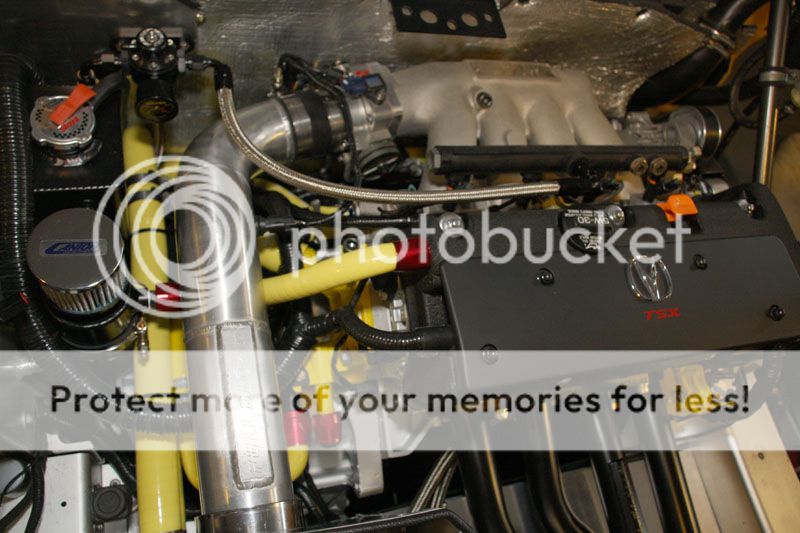
I'm pretty much wrapped up with the exception of a couple additional hoses on order (7-8 week lead time on the custom yellow silicone hose). I'm not quite sure why the silicone looks washed out in the photos, but on the car it looks really nice.

I really like the red aluminum hose clamps for the valve cover / oil catch can.
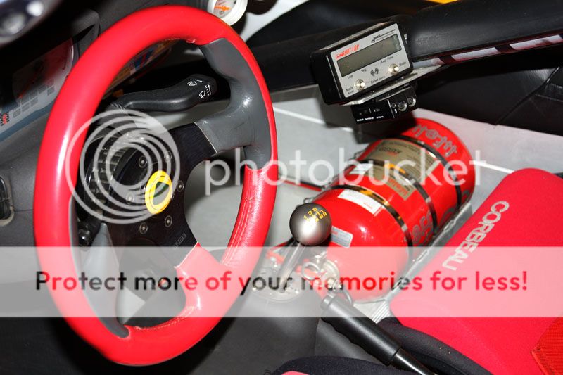
Now it's time to start installing the GPS Trackmate Data Logger & HD Camera System. It will monitor a lot of sensors on the engine (RPM, Brake, TPS, Oil Temp, Oil Pressure, etc). All the data will overlay on top of the edited video. I also plan to hard wire a microphone in the engine bay (for the video).
Pulled the driver's seat to gain access to the area where I wanted to mount the Traqmate Sensor Unit with HD Data Module for HD Camera Control from dash and various digital/analog engine inputs (i.e. RPM). I also permanently wired a camera power supply so I don't have to worry about camera battery power.
I also installed a Shift-i progressive shift light system that is fully programmable. The green LED's start at the beginning of the powerband slowly building through amber... then red... for optimum gear management assistance through peripheral vision.
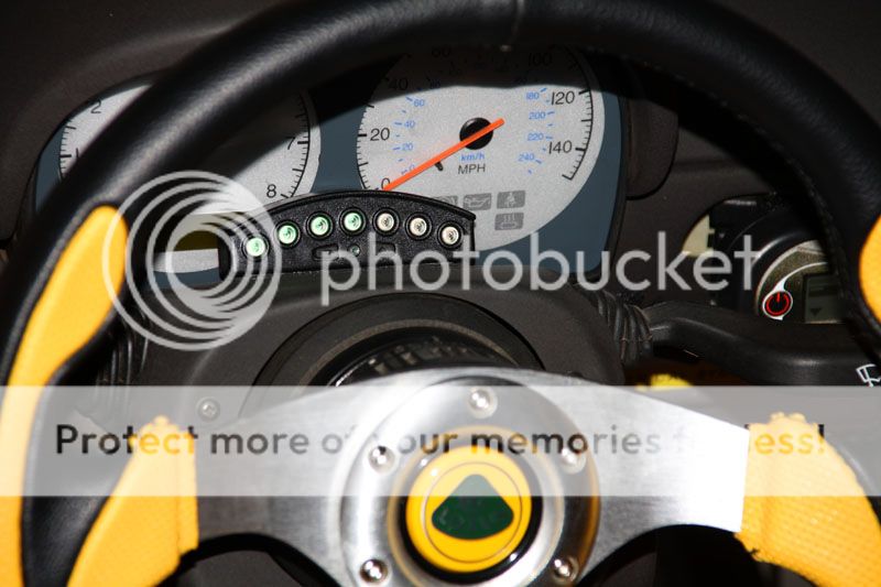
Here's the remote Traqmate Display Unit mounted to the dash. It's backlit and allows selection of drivers, tracks, camera control, as well as real time display of engine sensors, speed, gear, rpm and lap times. All data is stored and downloaded to my laptop from here (USB Port on the side).
Some may be wondering what the two bullet lights are on top of the instrument stack binnacle? These were installed by the car's previous owner. I had planned to remove them and replace the plastic binnacle with a new one (without holes in the top) until I learned a new binnacle is $250. Maybe they don't look so bad after all? I wired the left amber light to the Hondata ECU MIL light output (malfunction indicator) and the red right light (which was the old shift light) is now an over-rev warning lamp (maybe 7800 rpm).

Finally the last of the silicone hoses arrived and I completed the last of the engine plumbing. That means the project is pretty much complete with regard to the swap/installation phase.

After filling with oil and coolant, I wanted to d a few tests prior to first start. The first test was a complete check of the electrical system, after all there were a lot of modifications made to the Acura loom and the lotus chassis wiring system.
Power on... turn key.... ECU MIL light on... then extinguishes. Good, the ECU likes what it sees. Fuel Pump fires up... 40+psi on the FPR gauge. I pulled the ignition connectors off the coil packs to cycle the engine to check for good oil pressure. Turn it over... slower at first... then after a few turns the engine momentum picks up speed (after good lubrication). Oil light goes out and oil pressure gauge needle shows good pressure.
The next step, checking the ECU for firmware version/update and base map upload. LJ with FullBlown Motorsports was kind enough to come over and assist with first start. After updating the ECU Hondata firmware, he input the injector tables and uploaded the base map. Looks good!
The time has come for first start... and video tells it better than words... right!! Woo Hoo!!
http://www.youtube.com/watch?v=M8nz9aVR5LM
Stay tuned... Mac out